COMMUNICATION BETWEEN ARDUINO AND RASPBERRY PI USING NRF24L01
1. Summary:
- This blog walks you through the process of how to communicate an Arduino and a Raspberry Pi with the nRF24L01 module. To Start off We will be learning Some basics of Raspberry Pi then we will have a look at Headless Raspberry Pi setup. For the Implementation Firstly, we will understand the simple communication of Arduino to Arduino then we will learn Arduino to raspberry pi.
- I found many guides to accomplish this around the Internet, but none of them was complete or fully worked for me. Here we will understand step by step guide of this process. And at the end will be showing a working example for the same.
2. Required Components:
- Ultrasonic Sensor
- 2 Arduino Uno
- Raspberry Pi 3
- 2 nRF24l01 transmitter and receiver
- Jump wires
- Arduino cable
- MINI USB 2.0 for Pi
- Breadboard
3. Required Software:
- Raspbian for pi
- Arduino IDE or Visual Studio
- Putty on remote computer for SSH
- VNC viewer on remote computer
4. Introduction to Raspberry Pi 3:
4.1. Components Specifications:
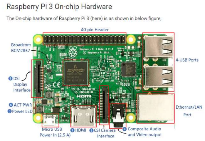
- 1.4 GHz 64-bit quad-core ARM Cortex-A53, 1GB RAM
- 2.4/5Ghz dual-band 802.11ac Wireless LAN, 10/100/1000Mbps Ethernet Bluetooth 4.2
- 4 USB ports, Full HDMI port, Combined 3.5mm audio jack, and composite video port, 40 GPIO pins
- Micro SD card slot, Video Core IV 3D graphics core, Camera interface (CSI), Display interface (DSI)
4.2. Raspberry Pi Pinout:
4.3. Headless Raspberry Pi Setup:
- Say, I just bought a raspberry pi and wish to check out how it works. But all I have is my Laptop, the Pi, a micro SD card and my Wi-Fi network. How do I connect and control the Pi?
1. Download Raspbian:
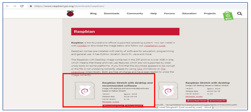
- Your Pi needs an OS. Download Raspbian from Raspberrypi.org ‘s download section:
- https://www.raspberrypi.org/downloads/raspbian/
2. Download SD Memory Card Formatter:
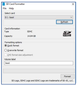
- It is used to format the SD card as it is needed that the SD card should be empty before flashing image you downloaded. You can download it from https://www.sdcard.org/downloads/formatter/eula_windows/
3. Flash it onto an SD card:
- You need to flash this downloaded image to the micro SD card. Assuming your laptop has an SD card slot or a micro Sd card reader, you need a flashing software like etcher. Go ahead and download from: https://etcher.io/
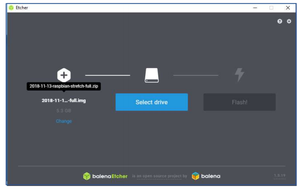
4. Configure Wi-Fi:
- It’s easier to make two devices talk to each other if they are in the same network. An ethernet cable can easily make your laptop’s network available to the Pi. But we don’t have one. So, we are going to add a file to the SD card so that the Pi boots with a wifi pre-configured.
- The SD card mounts as two volumes boot and rootfs. Open the boot volume and create a file named wpa_supplicant.conf on booting the RPi, this file will be copied to /etc/wpa_supplicant directory in /rootfs partition. The copied file tells the Pi the WIFI setup information. This would overwrite any existing WIFI configuration, so if you had already configured WIFI on the pi, then that will be overwritten.
- A typical wpa_supplicant.conf file is as follows:
ctrl_interface=DIR=/var/run/wpa_supplicant GROUP=netdev
update_config=1
country=US
network={
  ssid="«your_SSID»"
  psk="«your_PSK»"
  key_mgmt=WPA-PSK
}
NOTE: Your SSID is your WIFI’s name. And psk is the password of the WI-FI.
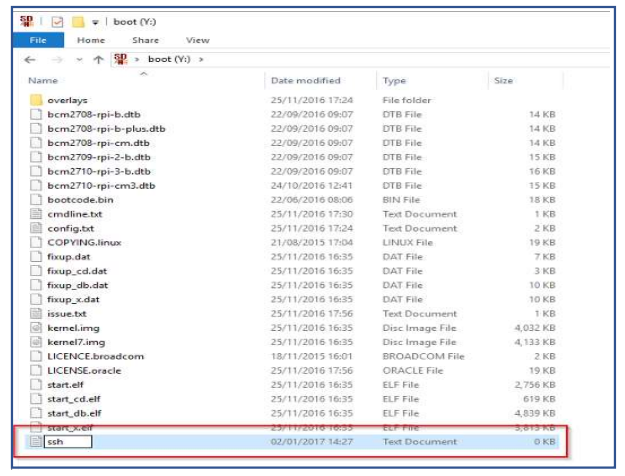
5. Enable SSH
- We will later access the Pi using a secured shell (SSH), SSH is disabled by default in Raspbian. To enable SSH, create a file named ssh in the boot partition. If you are on Linux, use the touch command to do that.
6. Find Pi’s Ip address:
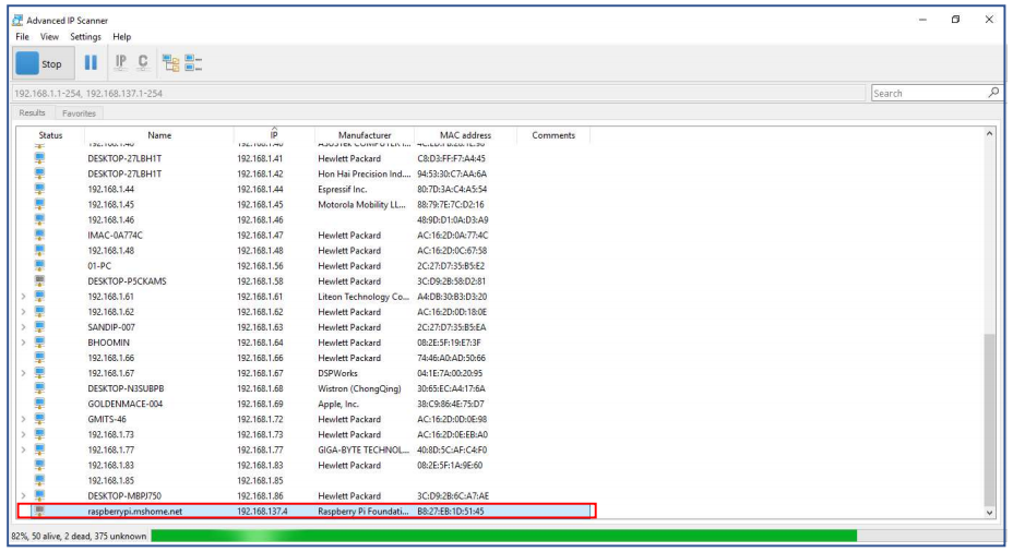
- Before switching on your raspberry pi, we need to find out the existing devices connected to the network. Make sure your laptop is connected to the same WIFI network as the one you configured on pi above.
- Download the Advanced IP Scanner to scan the IP of our raspberry pi. You can download it from here https://www.advanced-ip-scanner.com/
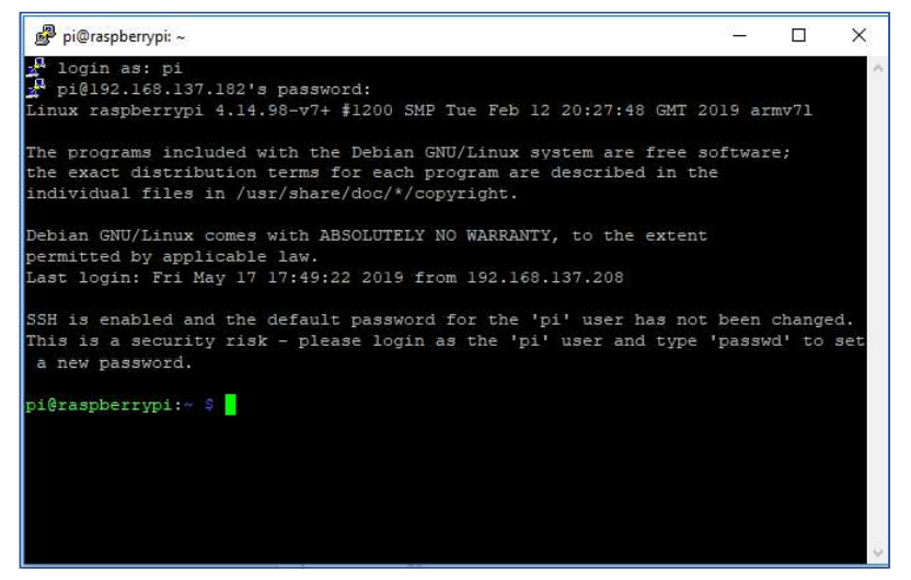
7. SSH into your Pi:
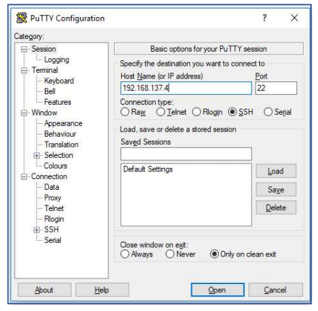
- To create a secured shell connection in Linux we can use the ssh command. If you are on windows, try downloading Putty from https://www.putty.org/
Default credentials are:
Username: pi
Password: raspberry
8. Access Pi remotely:
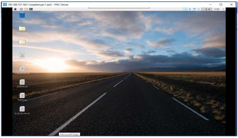
- Sometimes it doesn’t feel right if we can’t use the mouse. For that, we need to look into the Raspbian desktop.
- We need to setup VNC (Virtual Network Connection) to see and control Pi graphically. Let’s do that.
- To access the remote desktop, you need VNC-viewer (client) for your laptop. Fortunately, RealVNC is available for a lot of OSes, pick one for your OS from https://www.realvnc.com/en/connect/download/viewer/
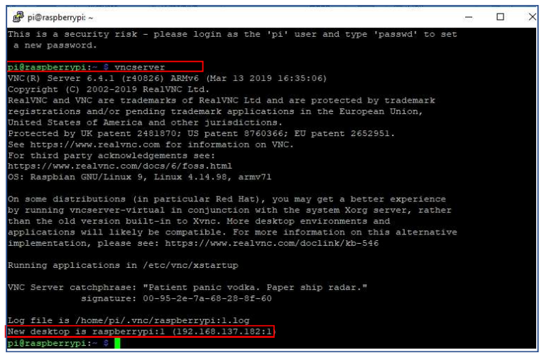
9. Commands for vncserver:
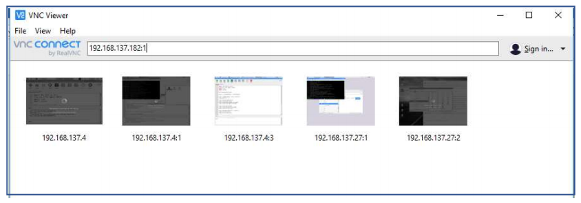
10. Now open VNC Viewer on your remote computer:
5. Implementation and Working:
5.1. Wireless communication of Arduino to Arduino with nRF24L01:
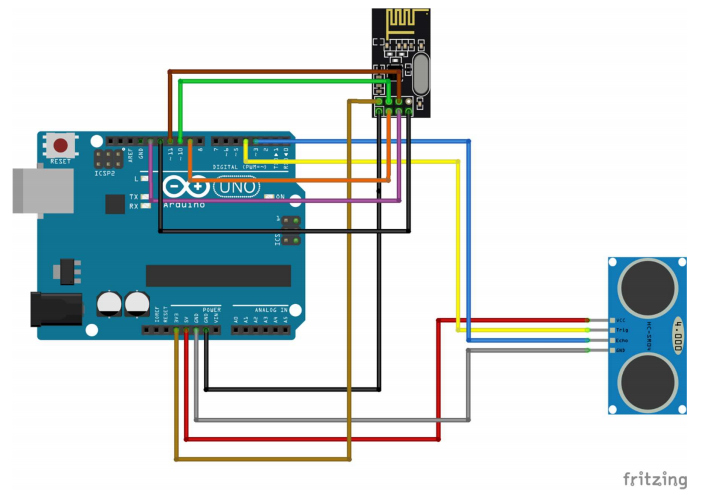
- In this, we will learn how to make wireless communication between two Arduino boards using the NRF24L01. And measure distance with ultrasonic sensor and transmit it to another Arduino with transceiver module.
Wiring Instructions:
To wire your NRF24L01+ wireless Sender to your Arduino, connect the following pins:
- Connect the VCC pin to 3.3 Volts
- Connect the GND pin to ground (GND)
- Connect the CE pin to Arduino 9
- Connect the CSN pin to Arduino 10
- Connect the SCK pin to Arduino 13
- Connect the MOSI pin to Arduino 11
- Connect the MISO pin to Arduino 12
To wire your ultrasonic sensor to your Arduino, connect the following pins:
- Connect the VCC pin to Arduino 5Volts
- Connect the GND pin to ground (GND)
- Connect the Trig pin to Arduino 4
- Connect the Echo pin to Arduino 3
To wire your NRF24L01+ wireless sender to your Arduino, connect the following pins:
- Connect the VCC pin to 3.3 Volts
- Connect the GND pin to ground (GND)
- Connect the CE pin to Arduino 9
- Connect the CSN pin to Arduino 10
- Connect the SCK pin to Arduino 13
- Connect the MOSI pin to Arduino 11
- Connect the MISO pin to Arduino 12
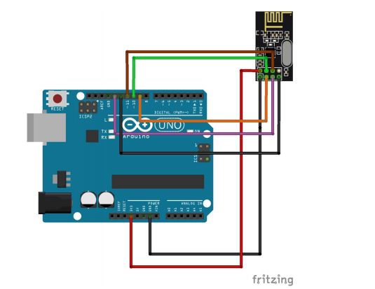
Schematic Diagram for wiring of Arduino Uno NRF24L01
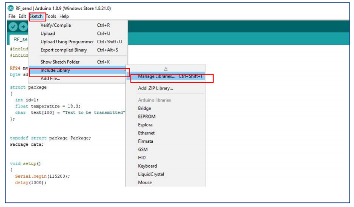
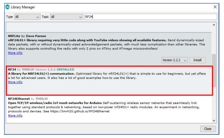
NOTE: RF24 module is mandatory for the code to run so you can add library accordingly
- Start Arduino IDE then add the Downloaded Library from Here :
5.2. Code:
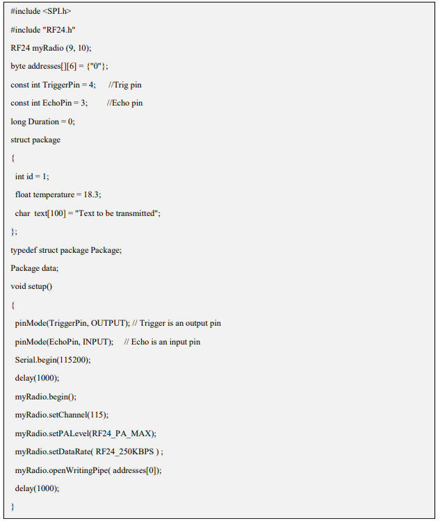
Sender Side code:
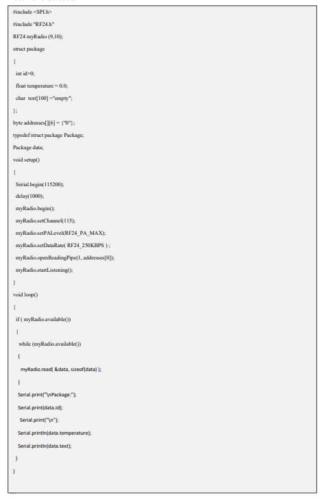
Receiver Side code:
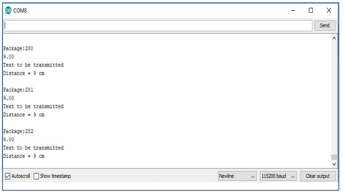
Sending the data:
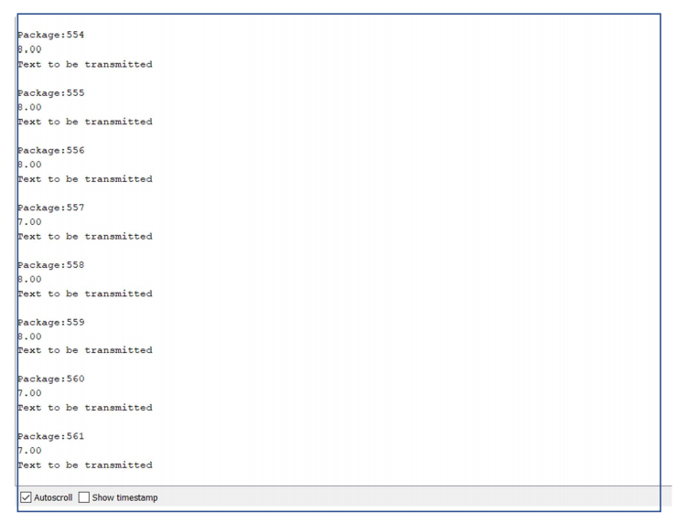
Receiving the data:
6. Wireless communication of Arduino to Raspberry Pi with nRF24L01:
6.1. Installation of RF24 Module on Raspberry Pi:
- It is most Important and foremost step for any Communication to work between Arduino and Raspberry Pi as we have used RF24 library in Arduino for communication so the same Library is needed on Pi.
- Further, are the steps to which involve the installation of Library. It took me almost one week to install it as no clear idea about it is present.
Way to go:
- Login to Raspberry Pi using Putty.
- Go to VNC server for GUI.
- In the terminal type:
sudo raspi-config
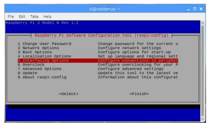
Turn on SPI from Interfacing options in config
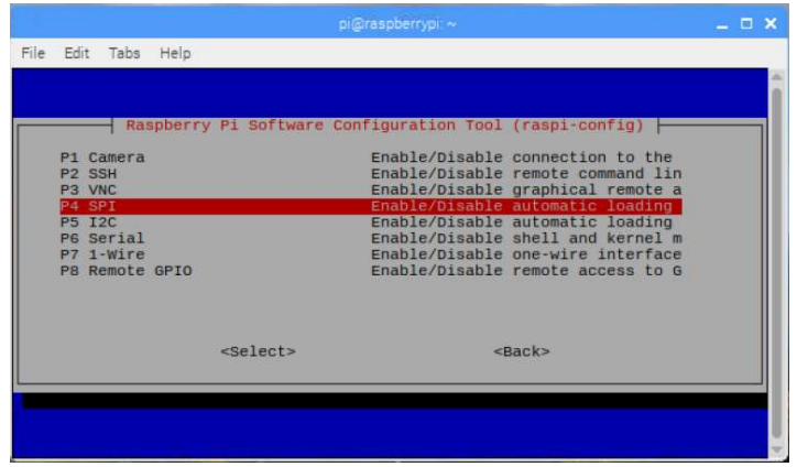
4. Reboot the Pi. In the terminal, type:
sudo reboot
5. In the terminal type:
sudo apt-get update
6. Download the install.sh file from http://tmrh20.github.io/RF24Installer/RPi/install.sh or Run this on terminal:
wget http://tmrh20.github.io/RF24Installer/RPi/install.sh
7. Make it executable:
chmod +x install.sh
8. Run it and choose your options:
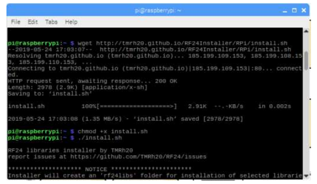
9. Run an example from one of the libraries:
cd rf24libs/RF24/examples_linux
make
sudo ./gettingstarted
Run Following Commands to run the program.
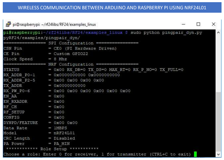
10. Further, if we want to run Python Programs for the same purpose, we can do this:
- Running the Example Edit the pingpair_dyn.py example to configure the appropriate pins per the above documentation:
nano pingpair_dyn.py
- Configure another device, Arduino or RPi with the pingpair_dyn example
- Run the example
sudo python pingpair_dyn.py
6.2. Wireless communication of Arduino to Arduino with nRF24L01:
- In this, we will learn how to make wireless communication between Arduino and Raspberry Pi using the NRF24L01. And measure distance with an ultrasonic sensor with the help of Arduino Uno and transmit it to Raspberry Pi and Data is received.
Wiring Instructions:
To wire your NRF24L01+ wireless Sender to your Arduino, connect the following pins:
- Connect the VCC pin to 3.3 Volts
- Connect the GND pin to ground (GND)
- Connect the CSN pin to Arduino 10
- Connect the CE pin to Arduino 9
- Connect the SCK pin to Arduino 13
- Connect the MISO pin to Arduino 12
- Connect the MOSI pin to Arduino 11
To wire your ultrasonic sensor to your Arduino, connect the following pins:
- Connect the VCC pin to Arduino 5Volts
- Connect the GND pin to ground (GND)
- Connect the Trig pin to Arduino 4
- Connect the Echo pin to Arduino 3
Schematic Diagram:
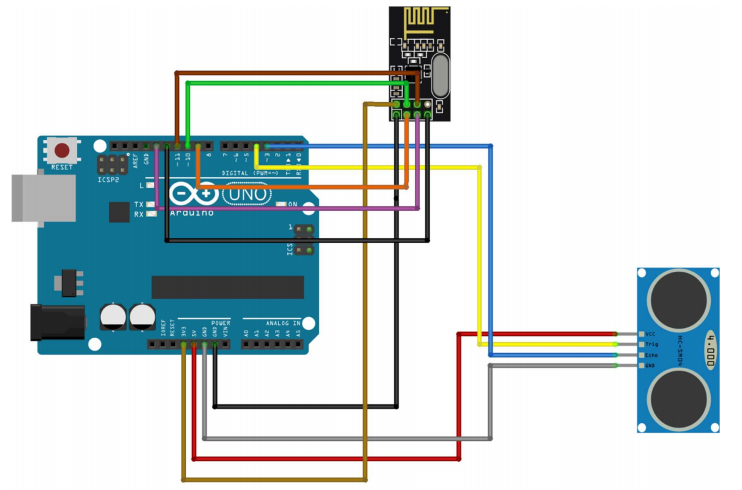
Schematic Diagram for wiring of Arduino Uno with ultrasonic sensor and NRF24L01
To wire your NRF24L01+ wireless Receiver to your Raspberry Pi, connect the following pins:
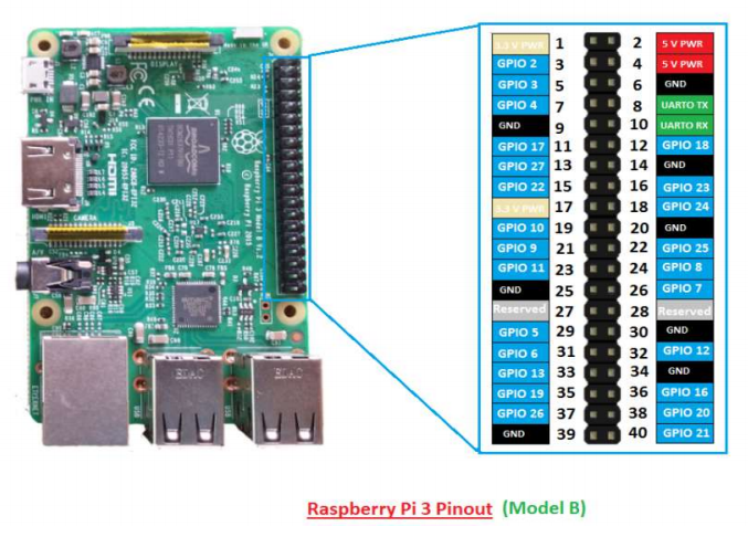
- Connect the VCC pin to 3.3 Volts (Pin 1)
- Connect the GND pin to ground (GND) (Pin 6)
- Connect the CE pin to Raspberry GPIO 22
- Connect the CSN pin to Raspberry GPIO 8
- Connect the SCK pin to Raspberry GPIO 11
- Connect the MOSI pin to Raspberry GPIO 10
- Connect the MISO pin to Raspberry GPIO 09
Schematic Diagram:
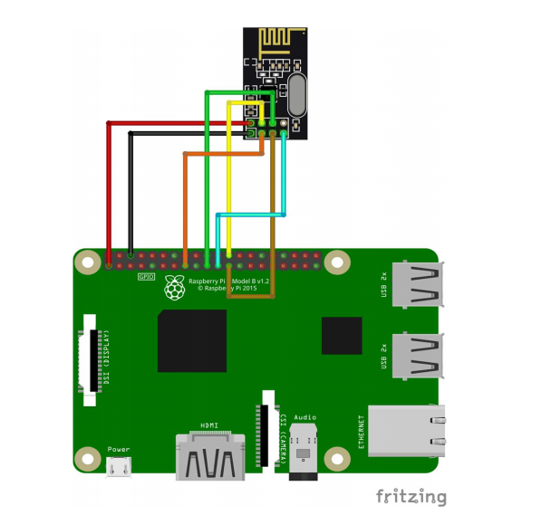
Schematic Diagram for wiring of Raspberry Pi and NRF24L01
6.3. Code:
- Sender Side Code: SendArduino.ino
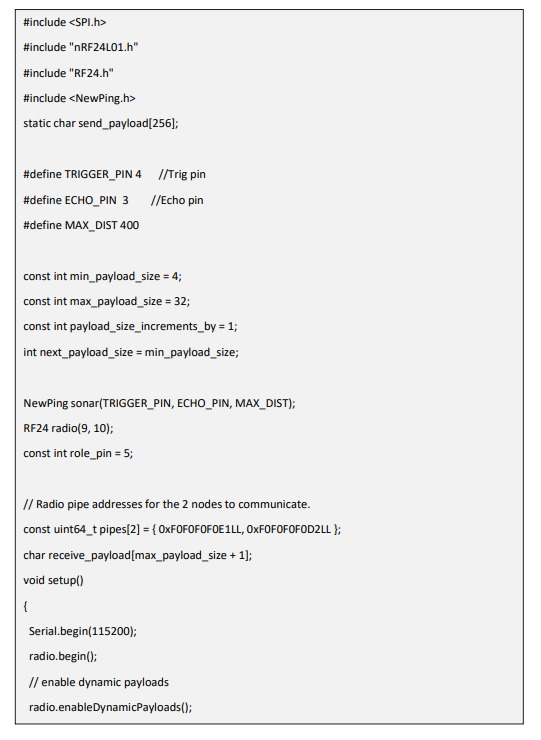
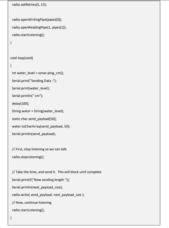
- ReceiveArduino.py:
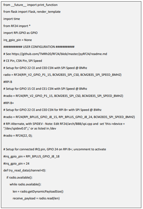
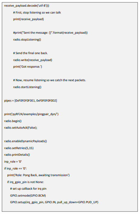
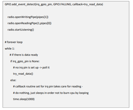
- It’s not mandatory to use this code as it is tweaked by me as per my requirement.
To check the proper functioning of your connection and code you can run the examples present in the library like pingpair_dyn.ino on your Arduino and pingpair_dyn.py on Raspberry Pi
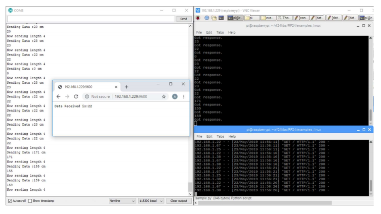
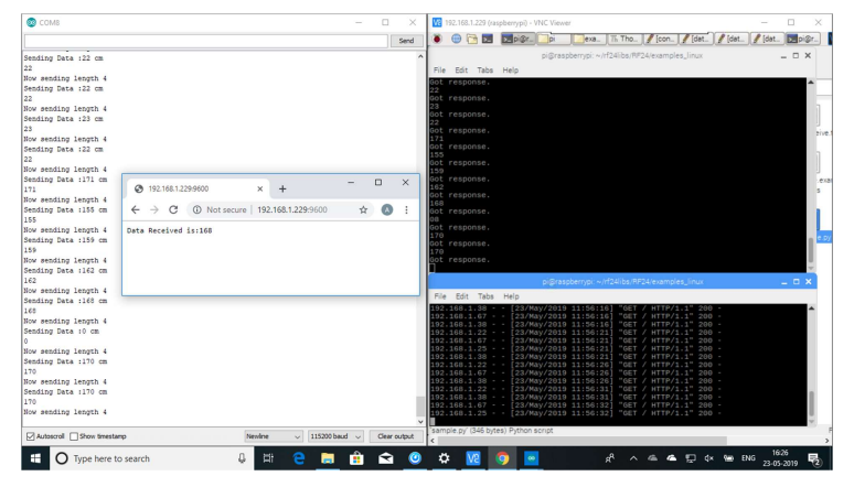
- A snippet of my running communication:
- A snippet of my running communication:
Conclusion:
It will be always fun experimenting and playing with the IoT Devices such as learning about Headless Raspberry Pi set-up, Arduino and Raspberry pi by making them communicating with each other and sending data and to overcome the errors and challenges like one I faced while installing RF24 module. The purpose of this tutorial is to serve you with the step-by-step process and hope that it was easy to follow and learn as well. Thank you for reading! Suggestions and Corrections are always welcome.
