NODE-MCU(ESP8266) WITH MQTT AND FIREBASE
This blog tutorial will bring you the brief idea about :-
- NodeMCU(ESP8266) Introduction and using it with well-known Arduino IDE.
- MQTT(MESSAGE QUEUED TELEMETRY TRANSPORT) protocol Introduction.
- Working of MQTT protocol with MOSQUITTO BROKER and its set-up
- MQTT protocol with NodeMCU on a local network with real-time example.
- Smart Home Automation using NodeMCU and MQTT with Firebase application and MOSQUITTO BROKER.
NODE-MCU(ESP8266)
1. Introduction
NodeMCU is open source platform, their hardware design is open for edit / modify / build. NodeMCU was created shortly after the ESP8266 came out. The ESP8266 is a Wi-Fi SoC integrated with a TensilicaXtensa LX106 core, widely used in IoT applications for wireless connectivity over Wi-Fi.
NodeMCU Dev board consist of ESP8266 wifi enabled chip. NodeMCU Development Board v1.0(Version 2) usually comes in black colored PCB.
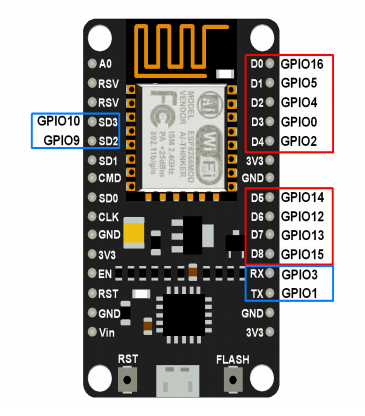
NodeMCU has Arduino like Analog (i.e. A0) and Digital (D0-D8) pins on board.
2. How to start with NodeMCU?
NodeMCU Development board is featured with wifi capability, analog pin, digital pins, and serial communication protocols.
To get started with using NodeMCU for IoT applications first we need to know about how to write/download in NodeMCU Development Boards.
After getting an idea about NodeMCU(ESP8266), let’s see the IDE (Integrated Development Environment)
required for development of NodeMCU.
3. Getting Started with NodeMCU using Arduino IDE
NodeMCU with a well-known IDE i.e. Arduino IDE. We can also develop NodeMCU applications using the Arduino development environment. This makes things easy for Arduino developers than learning a new language and IDE for NodeMCU.
Arduino IDE does not have pre-installed NodeMCU board. It has to be set up manually.
Let’s see about setting up NodeMCU on Arduino IDE.
- Download Arduino IDE
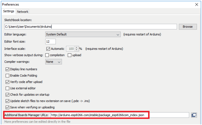
- Open Arduino IDE and Go to File –> Preferences.
- Now on Preference window, enter the following link in Additional Boards Manager URLs
http://arduino.esp8266.com/stable/package_esp8266com_index.json
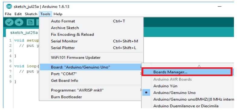
Now close Preference window and go to Tools -> Board -> Boards Manager
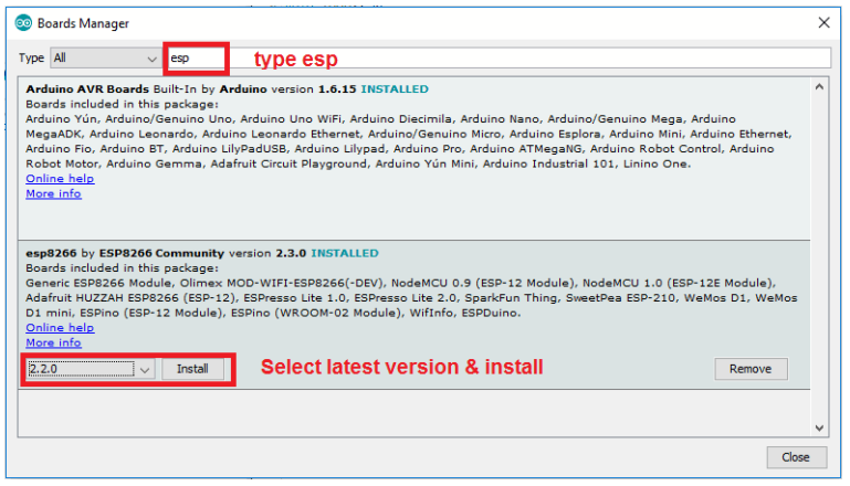
- In Boards Manager window, Type esp in the search box, esp8266 will be listed there below.
Now select the latest version of the board and click on install.
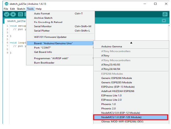
- After installation of the board is complete, open Tools->Board->and select NodeMCU 1.0(ESP-12E Module).
Now Your Arduino IDE is ready for NodeMCU. A sketch can be written and uploaded to NodeMCU same as Arduino.
MQTT(MESSAGE QUEUED TELEMETRY TRANSPORT) PROTOCOL WITH NODE-MCU(ESP8266)
1. INTRODUCTION:
MQTT stands for Message Queued Telemetry Transport. It is a publish/subscribe, extremely simple and lightweight messaging protocol, designed for constrained devices and low-bandwidth, high-latency or unreliable networks. The design principles focus on minimizing network bandwidth and device resource requirements whilst also attempting to ensure reliability and some degree of assurance of delivery. These principles also turn out to make the protocol ideal of the emerging “machine-to-machine” (M2M) or “Internet
of Things” world of connected devices, and for mobile applications where bandwidth and battery power are prime concerns. This protocol is designed for data transfer between devices with limited network bandwidth and power. Thus it is highly recommended for microcontroller based projects that send data over the internet.
2. HOW MQTT WORKS:
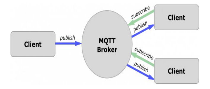
Communication through MQTT needs a “broker” which is responsible for distributing messages to clients based on a certain topic . A publisher sends data to the broker while subscribers reads data from the broker.
MQTT server is called a broker and the clients are simply the connected devices.
When a device (a client) wants to send data to the broker, we call this operation a “publish”.
When a device (a client) wants to receive data from the broker, we call this operation a “subscribe”.
3. WHICH BROKER TO USE:
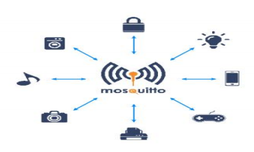
There are many brokers that implement the MQTT protocol. One of the most popular and commonly used is the mosquitto broker.
Mosquitto is an open source message broker that implements the MQTT protocol. It’s lightweight and suitable for use on all devices from a low power single board like Arduino, ESP8266 to full computers and servers.
But rather than using the Mosquitto on a local PC, you will need to use a cloud-based server that implements the Mosquitto broker. That’s necessary to make your IoT projects controllable over the internet.
CloudMQTT is one of the best and easiest cloud-based Mosquitto broker. CloudMQTT has a free plan that allows you to set up your own CloudMQTT broker instance that will run on their hardware servers. Hence, you can have an online broker that’s ready to use in your IoT project. It also has a well designed GUI to monitor the publishing and subscribing processes and topics through an easy to use WebSocket UI.
Also available web-based brokers like Adafruit IO and shifr.io.
To understand how MQTT can be applied to On IoT project let’s create a mini IoT project to control the LEDs on the Nodemcu using python program on PC and mosquitto as MQTT broker.
4. MQTT protocol Working with Mosquitto Broker and the NodeMCU board :
4. MQTT protocol Working with Mosquitto Broker and the NodeMCU board :
Installing Mosquitto MQTT broker.
Setting up NodeMCU with LEDS and MQTT client code.
Creating remote MQTT client to interact with NodeMCU (Here we will create python client using paho.mqtt library )
REQUIRED COMPONENTS ARE:-
– NodeMCU
– USB Cable
– LED
– Arduino IDE
Step-1: INSTALLING Mosquito MQTT broker:
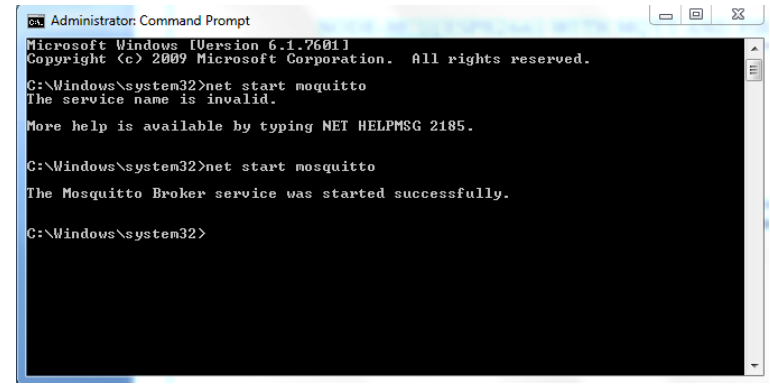
- First install the mosquito broker on PC from below link:-
https://mosquitto.org/download/ - After installing MOSQUITTO BROKER start the service using:- net start mosquito(if you are using windows os then you will require to open cmd as an administrator to run above command)
- To test the MOSQUITTO BROKER service started:-
In separate terminals in Windows(CMD) execute the following commands:-
(All command must be run in C:\Program Files\mosquitto directory)
- Start the broker:
mosquitto - Start the command line subscriber:
mosquitto_sub -t “test/topic” - Publish test message with the command line publisher:
mosquitto_pub -t “test/topic” -m “helloWorld”
Step-2: Setting up the Nodemcu with LED’S and MQTT CLIENT:
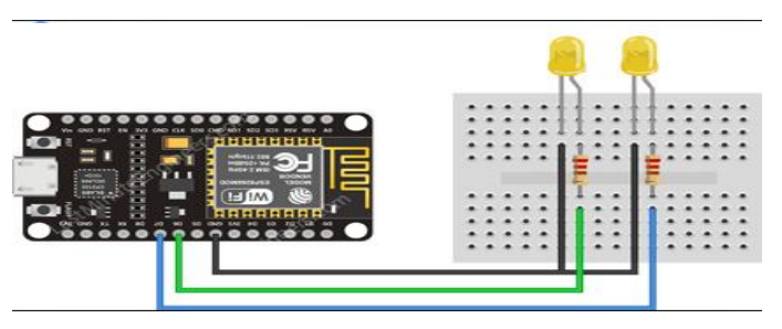
- Connecting LEDs :-
Connect the leds with pins D7(GPIO13) and D6(GPIO12) as shown:-
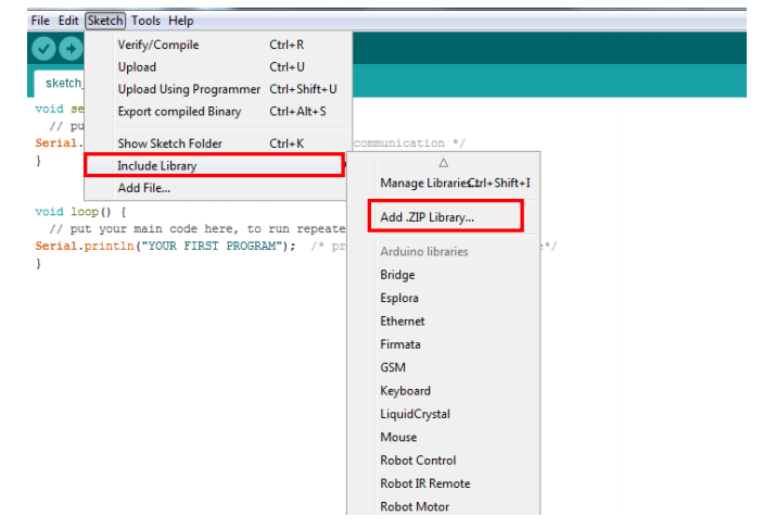
- Install PubSubClientlibrary in Arduino IDE
- 1. We need to install MQTT endpoint library(PubSubClient) to communicate with MQTT broker, please download the library from the following link:
http://osoyoo.com/wp-content/uploads/samplecode/pubsubclient.zip
2. Open Arduino IDE–>Sketch->Include library ->Add Zip library, then add your zip file.
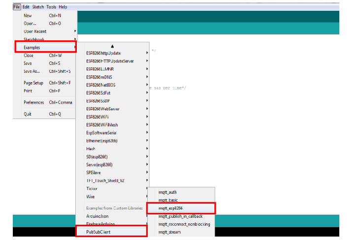
3. Open Arduino IDE–>File–>Example–>pubsubclient–>mqtt esp8266, you will get sample code.
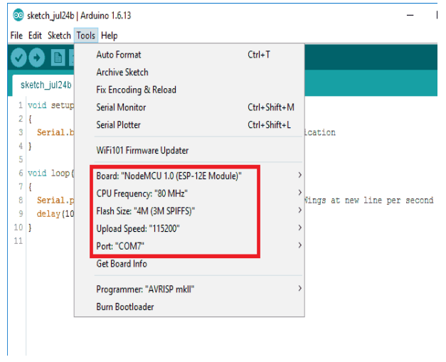
4. In sample code make necessary changes of the board and ports settings as shown below:
- Edit the code to fit your own WiFi and MQTT settings as following operations:
- Hotspot Configration: Find below code line,put your own ssid and password on there.
const char* ssid = “your_hotspot_ssid”;
const char* password = “your_hotspot_password”;
2. MQTT Server Address Setting, here we use free MQTT broker “your device ip address such as laptop”You can use your own MQTT broker URL or IP address to set above mqtt_server value. You can also use some famous free MQTT server to test the project such as “broker.mqtt-dashboard.com”, “iot.eclipse.org” etc using CLOUD MQTT.
const char* mqtt_server = “broker.mqtt-dashboard.com”;#for CLOUD MQTT
BROKER
const char* mqtt_server = “192.168.1.51”#for MQTT BROKER LIKEMOSQUITTO
We will use the IP of the PC (where mosquito broker is running) as MQTT server addresses
3. MQTT Client Settings:
If your MQTT broker require clientID,username and password authentication,you need to change
if (client.connect(clientId.c_str()))
To
if
(client.connect(clientId,userName,passWord))   //putuourlientId/userName/password here
If not,just keep them as default such as in our case.
4. Add logic to control the LED:
In the reconnect function, change the subscribe topic to “led”. We will publish a message on this topic from Python MQTT client.
client.subscribe("led");
We will also add logic to light-up the led based on the received message. Modify the callback method as follow:
void callback(char* topic, byte* payload, unsigned int length) {
Serial.print("Message arrived [");
Serial.print(topic);
Serial.print("] ");
  String s="";
  for (int i = 0; i< length; i++) {
   Serial.print((char)payload[i]);
   s=s+(char)payload[i];
  }
 int in=s.toInt();
 switch (in)
 {
  case 1: digitalWrite(13, HIGH);
  digitalWrite(12, LOW);
  break;

  case 2: digitalWrite(12, HIGH);
  digitalWrite(13, LOW);
  break;
 }
(You can comment the instruction to publish “hello world” in loop function as we are not publishing any message)
• After that, choose the corresponding board type and port type as below, then upload the sketch to the nodeMCU.
- Once the upload is done(the same way is shown above), if the wifi hotspot name and password setting is ok, and MQTT broker is connected, open the Serial Monitor(in the same way as above or
CTRL+SHIFT+M), you will see your the publish message on the serial monitor as an output.
Step- 3: Creating MQTT client using python
• First, install the Python Paho MQTT library. Type following in a terminal:
pip install paho-mqtt #install the PAHO MQTT client
After installing the paho python library lets start with coding,
• Followings are steps to code Python MQTT client:
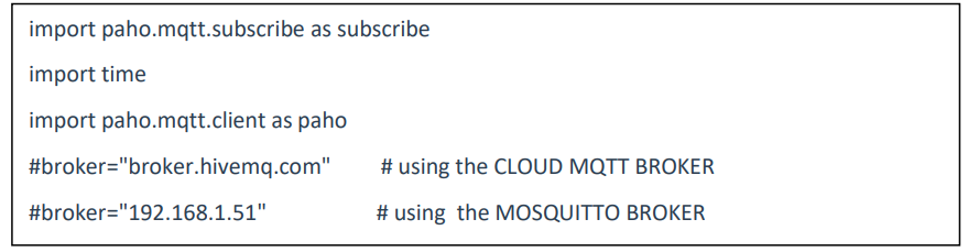
STEP-1:
Import the paho.mqtt.client module after the installation.
Create variable the broker which stores the address of MQTT broker. It can be the URL of the broker such as in case you are using CloudMQTT broker or it can be IP of the host pc where the broker is running as in our case.
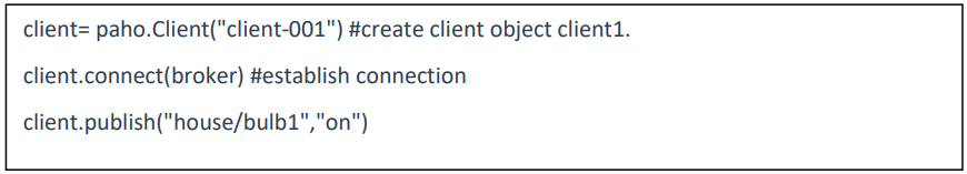
STEP-2:
Create the client object using paho.Client(). It takes one string argument which is assigned as ID to the newly created client. Establish a connection to broker using connect() method.It takes one parameter: address of broker. The client can publish the message with publish() method. In the following example the client will publish “on” to topic “house/bulb1”.
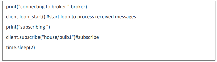
STEP-3:
After connection with MQTT BROKER and the MQTT client can subscribe to receive
published message using the subscribe() method.
(This step is just for understanding. You can skip this as we are never going to receive any
message.)
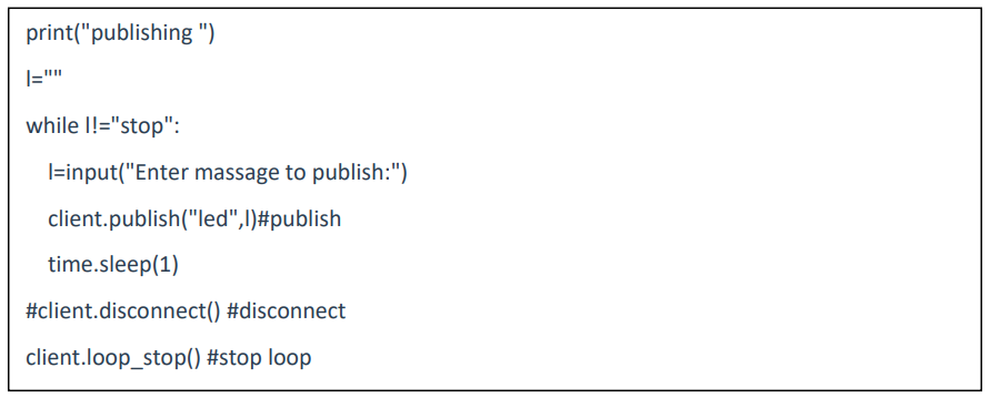
STEP-4:
Following code takes input from the user and publish it to topic “led”. client.disconnect()
is used to disconnect the client from the broker.
STEP-5:
Run the python program.
- For input “1” led at D7 will turn on and D6 will be turned off.
- For input “2” led at D7 will turn on and D6 will be turned off.
We can connect electronics devices (Lights, fans, bulbs, etc.) using the relay module. An android client can be developed using the paho repository to control them.
5. MQTT REAL TIME EXAMPLE FOR HOME AUTOMATION SYSTEM WITHIN LOCAL NETWORK:
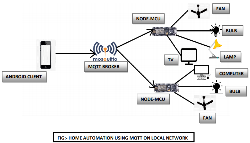
THE MQTT allows the smart home devices to communicate with a home assistant or any other MQTT Broker. The home assistant also runs on the MQTT Broker and MOSQUITO BROKER is highly recommended rather than using the remote broker like CLOUD MQTT which requires internet connectivity in smart home devices.
Also, all the smart home devices are within the home network so MOSQUITTO MQTT is more reliable.
In this, the MQTT transmission will be done by three parts:- message, topic, QoS Packet
If a user wants to turn on the hall light “on” then user’s MQTT client (such as smartphone app) will publish the topic as “lights ” and message as “ON” to MQTT BROKER and that broker will then post the message to that specific topic. The devices which have subscribed to that topic will then receive the message and TURN ON the lights.
Here MQTT BROKER knows about clients history, clients ID and which clients are subscribed to particular topics and it also the currently connected clients as it will send the keep-alive message to broker in specific time, they keep live timeout is set by the MQTT BROKER AS DEFAULT IS 60 SECONDS IN MOSQUITTO BROKER SO LIGHT CAN BE ON FOR 60 SECOND which can be changed as per requirement.
QoS packet used by MQTT BROKER is QoS 2: EXACTLY ONCE which means that for each data send the immediate ack is received by MQTT BROKER from the devices.
SMART HOME AUTOMATION USING NODE-MCU AND MQTT WITH FIREBASE APPLICATION AND MOSQUITTO BROKER.
1.Introduction:
In this section, we will learn about smart home automation using NODE-MCU and FIREBASE. It will require you to install the Firebase library in Arduino IDE and to simplify the coding is divided into three parts, So let ‘s get started:-
Required components are:-
- NodeMCU
- USB Cable
- PC
- Arduino IDE
- Connect the NodeMCU to PC via USB cable.
CIRCUIT SET-UP OF LED’S CONNECTION WITH NODE-MCU:-
2. Node-MCU Firebase connection:
To code, the program for Firebase connectivity to NodeMCU FirebaseArduino library is used. If it is not available in Arduino IDE then add to the Arduino library.
https://codeload.github.com/FirebaseExtended/firebase-arduino/zip/master
To get the example code goto File–>Examples–>FiraebaseArduino–>FirebaseDemo_ESP8266
The whole program can be divided into three steps:
Step-1:- Wi-fi connection to provide internet.
Step-2:- Firebase connectivity
Step-3:- Data stream
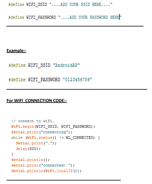
Step – 1: -WIFI connectivity to provide internet:-
The WIFI connect in this process requires two main things to be mentioned in code and must be changed by user is SSID and PASSWORD of user WIFI connectivity:
General:-
Step-2:- FIREBASE connectivity:
- Go to google firebase console and log in with google account.
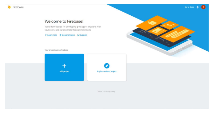
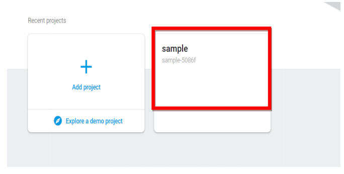
- Click on “Add project” to create a project.
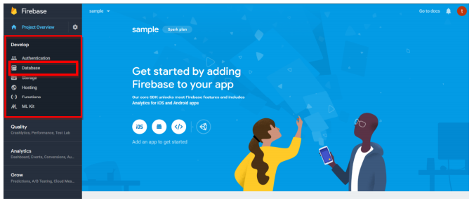
- After creating the project click on your project icon
- Click on Database which is in Develop option in the side menu.
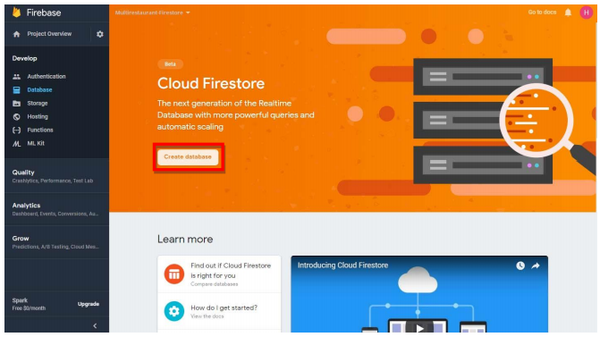
- Click on create the database.
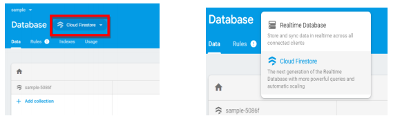
- Select Realtime database from the dropdown which is just beside Database in the blue title bar.
- Add field ‘s1’ by clicking on +.
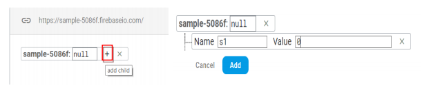
- Firebase project URL and Authentication key are required to connect with Firebase.
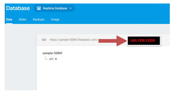
- Get the URL as shown above. Remove https:// and / after ‘.com’
Steps to obtain the AUTHENTICATION_KEY:-
Step-1:- In google firebase console in Realtime Database the AUTHENTICATION_KEY can be obtained as mentioned below:-
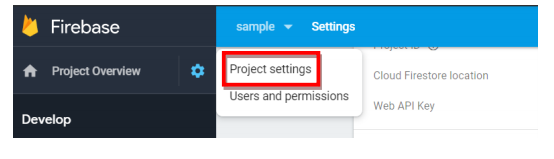
- Go to Project settings under setting icon beside Project overview.
- Go to Service accounts>Database secretes.
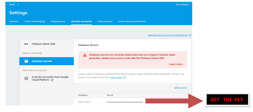
- Hover the mouse over hidden key then click on Show.
Step-2:- Define Firebase FIREBASE_HOST and AUTHENTICATION_KEY with obtained URL and key.
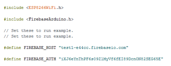
Connecting with firebase:-
Step-3:- DATA STREAMING:-
- Firebase.getInt(“field-name”) is used to get the value of specified Intfield. Similarly getFloat() and getString() is used to retrieve Float and String fields.
- Firebase.setInt(“field-name”, value) is used to set value of specified field. Similarly getFloat() and getString() is used to set Float and String fields.
- Now the code for obtaining output on LED for testing can be as below:-
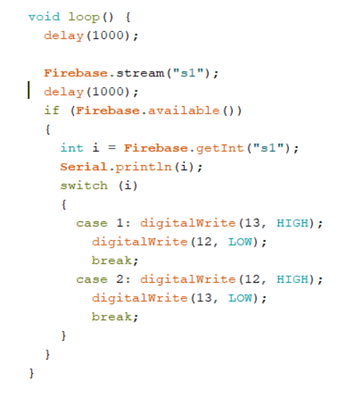
- [IMPORTANT NOTE:– The pins in the above code refers to the D6 and D7 as 13 and 12
respectively which is to be changed by the user as per LED connected with Node MCU pins]
➢ At last, run the code by making necessary changes mentioned and as per the input by user, the respected LED will light up for e.g.:- if the user enters 1 then first LED will light up where data are live and output is obtained.
➢ In real time instead of LED, the HOME APPLIANCES such as bulb can work on the user commands in HOME AUTOMATION SYSTEMWe can create an app or web service using Firebase API to send the input over firebase. So than let ‘s learn to create the application with Firebase
6. Creating Android app using the Firebase Assistant:-
The purpose of creating this application with Firebase would help you to control HOME DEVICES in real time implementation of such system at large scale Guidance for creating android app to integrate firebase realtime database is available on following
link:-
https://firebase.google.com/docs/database/android/start
7. Basic Real-time implementation Architecture and Example with Firebase
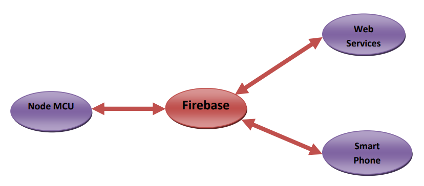
- Let’s say there is a device that has a temperature sensor. Certainly, it wants to send his readings to the Firebase. On the other side, a phone/desktop application wants to receive this temperature value. Therefore, two things will happen:
- The device defines the topic it wants to publish on, ex: “temp” as a field in FIREBASE REALTIME DATABASE instead of s1 in the above code. Then, it publishes the message “temperature value”.
- The phone/desktop application subscribes to the topic “temp”. Then, it receives the message that the device has published, which is the temperature value.
- Again, the broker role here is to take the message “temperature value” and deliver it to phone/desktop application.Now you are all set to play with your all Home Appliances with the completion of this section using Firebase application with control in your hands in your smart home automation system.
Conclusion: Hope that it was fun working for you with IoT Devices such as Node-MCU(ESP8266) and further using it with well known Arduino IDE and the MOSQUITTO BROKER, also exploring the MQTT(Message Queued Telemetry Transport ) protocol on the local network with real-time example and joy of designing the Smart Home Automation System and having control in your hands. The purpose was to simplify content and allow you to gain knowledge and learn in as much as an easy way possible.