NOTE: Your SSID is your WIFI’s name. And psk is the password of the WI-FI.
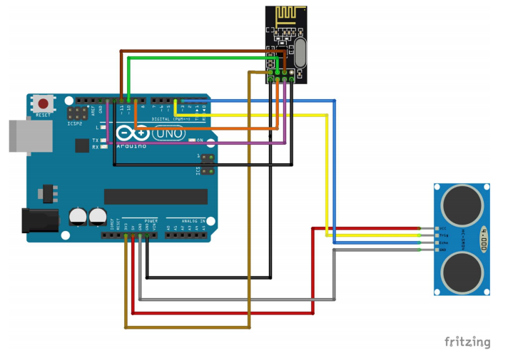
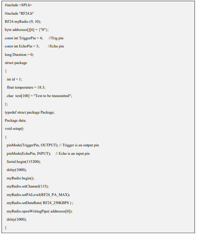
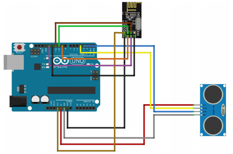
To wire your NRF24L01+ wireless Sender to your Arduino, connect the following pins:
To wire your ultrasonic sensor to your Arduino, connect the following pins:
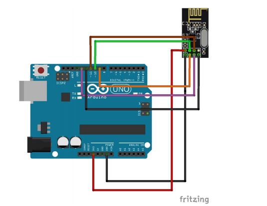
To wire your NRF24L01+ wireless sender to your Arduino, connect the following pins:
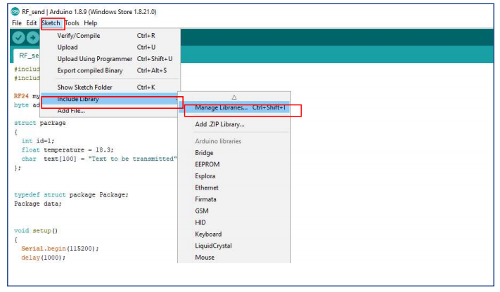
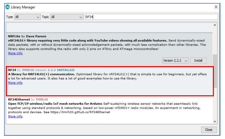
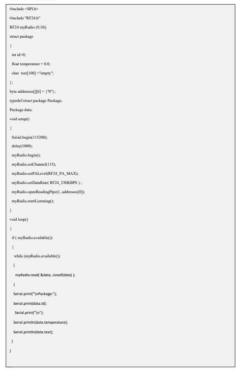
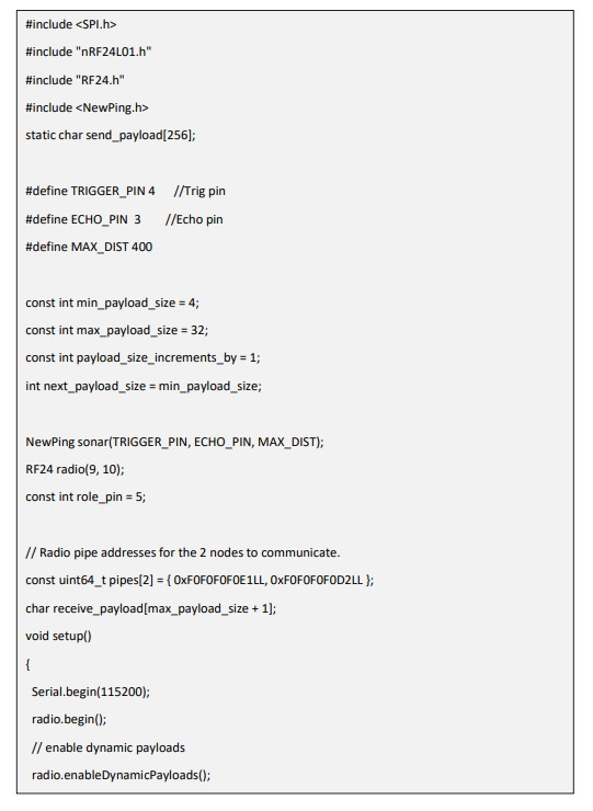
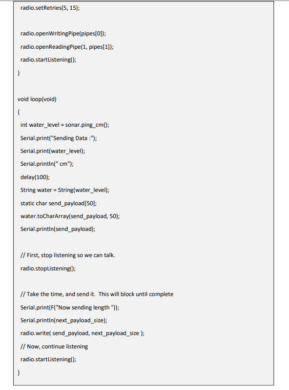
NOTE: RF24 module is mandatory for the code to run so you can add library accordingly
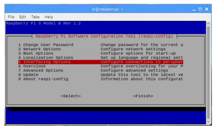
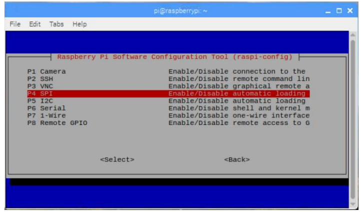
Turn on SPI from Interfacing options in config
4. Reboot the Pi. In the terminal, type:
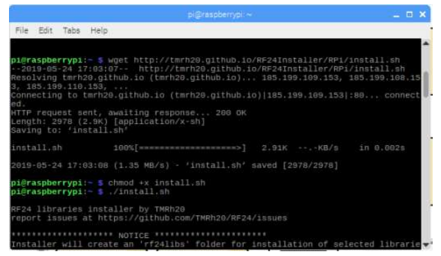
6. Download the install.sh file from http://tmrh20.github.io/RF24Installer/RPi/install.sh or Run this on terminal:
8. Run it and choose your options:
9. Run an example from one of the libraries:
Run Following Commands to run the program.
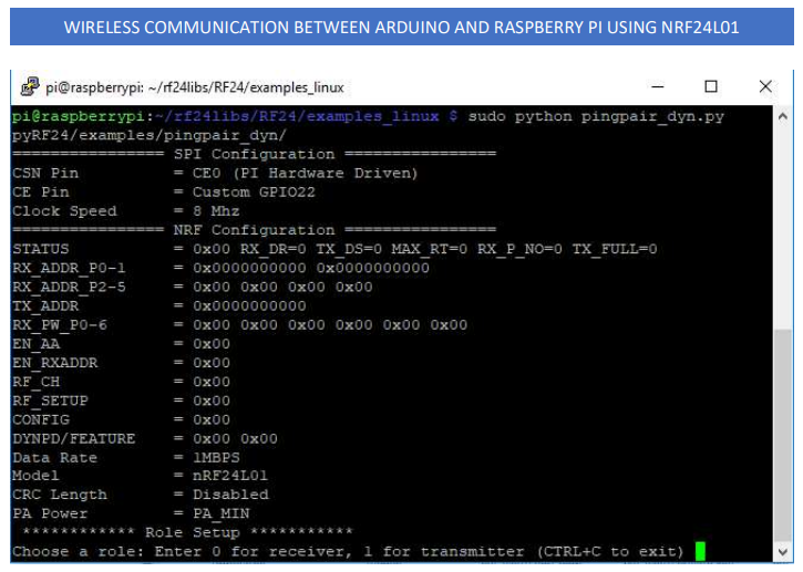
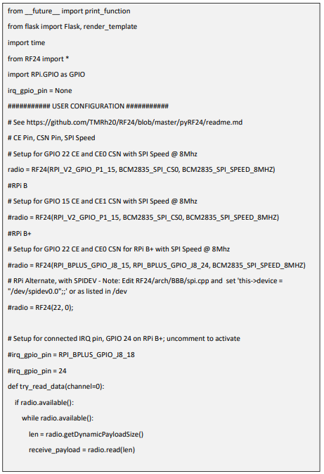
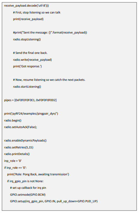
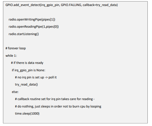
10. Further, if we want to run Python Programs for the same purpose, we can do this:
To wire your NRF24L01+ wireless Sender to your Arduino, connect the following pins:
To wire your ultrasonic sensor to your Arduino, connect the following pins:
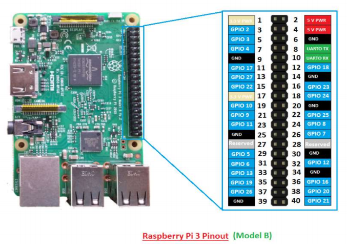
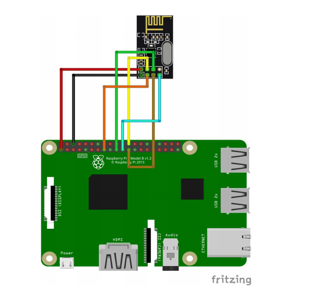
To wire your NRF24L01+ wireless Receiver to your Raspberry Pi, connect the following pins:
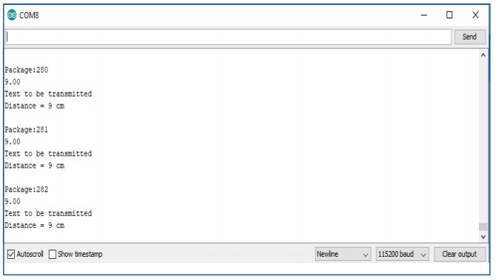
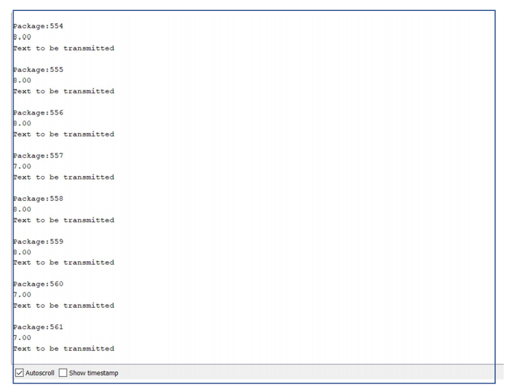
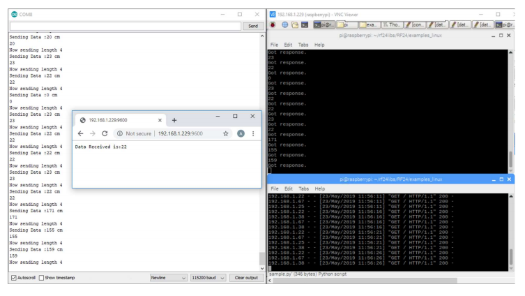
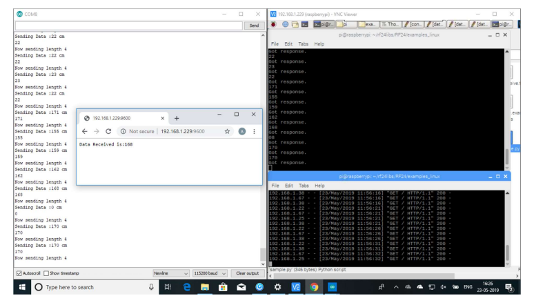
To check the proper functioning of your connection and code you can run the examples present in the library like pingpair_dyn.ino on your Arduino and pingpair_dyn.py on Raspberry Pi
It will be always fun experimenting and playing with the IoT Devices such as learning about Headless Raspberry Pi set-up, Arduino and Raspberry pi by making them communicating with each other and sending data and to overcome the errors and challenges like one I faced while installing RF24 module. The purpose of this tutorial is to serve you with the step-by-step process and hope that it was easy to follow and learn as well. Thank you for reading! Suggestions and Corrections are always welcome.